
W.Y.
Member
I have revived this thread from when I made the disk part because I have just recently been able to get back in my shop after the table saw kick back accident..
I made the next step of my segment sanding jig setup this afternoon. .
Here is what it looks like up close to the 12" sanding disk . The sanding disk is still running with zero run-out so I figure it will continue to do so.
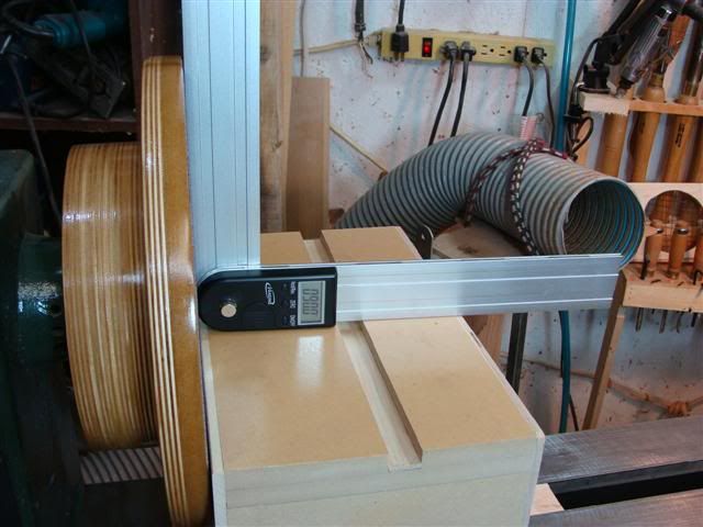
A little better closeup shows that the table is 090.00 degrees to the disk.

This one shows a standard T square in the slot.

And this one shows what the hole in the end is for .
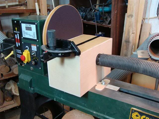
The slit in the right side in this picture is the part that faces the disk on the left side when the unit is fastened onto the lathe to correspond with the downward direction of the disk on the left side. . The theory is that if the cubic inch displacement of the slot is a little smaller than the vacuum being applied from the opposite side, that a high volume of vacuum will be created inside the "box" to remove the sanding dust. . I have not tried it yet because I wanted to show the pictures before it got dirty with use so I will know later how well the dust extraction theory works.
Next stage will be to make up the jig that Malcolm Tibbetts shows in his DVDs but first I am going to apply enough coats of polyurethane to this stage of the project until it will not absorb any more and produces a nice finish..
Heck . . . I might even get carried away and paint it instead

I made the next step of my segment sanding jig setup this afternoon. .
Here is what it looks like up close to the 12" sanding disk . The sanding disk is still running with zero run-out so I figure it will continue to do so.
A little better closeup shows that the table is 090.00 degrees to the disk.
This one shows a standard T square in the slot.
And this one shows what the hole in the end is for .
The slit in the right side in this picture is the part that faces the disk on the left side when the unit is fastened onto the lathe to correspond with the downward direction of the disk on the left side. . The theory is that if the cubic inch displacement of the slot is a little smaller than the vacuum being applied from the opposite side, that a high volume of vacuum will be created inside the "box" to remove the sanding dust. . I have not tried it yet because I wanted to show the pictures before it got dirty with use so I will know later how well the dust extraction theory works.
Next stage will be to make up the jig that Malcolm Tibbetts shows in his DVDs but first I am going to apply enough coats of polyurethane to this stage of the project until it will not absorb any more and produces a nice finish..
Heck . . . I might even get carried away and paint it instead
 Will break it in after I get the segmenting jig made to go with it which was one of the purposes I have made this set-up for.

